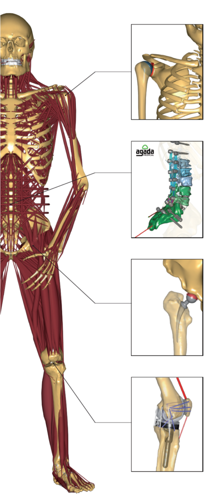
The AnyBody Modeling System can be used to evaluate how activities of daily living are affected by the shape and positioning of an implant. It allows joint motion, stability, and soft tissue balancing to be quantified through simulation.
The detailed joint analysis is typically done using an analysis type called Force Dependent Kinematics™. This allows the motion of specific degrees of freedom (DOFs) in the model to be predicted. The detailed joint modeling includes contact forces between implants, muscles, and ligament forces. Using this approach, the AnyBody Modeling System has been used to win the Grand Knee Challenge (Scientific competition on predicting in vivo knee loads) multiple times.
Examples:
- Anatomical ACL reconstruction
- Natural Knee Kinematics
- Physiological realistic loads for activities of daily living
- Mechanical and kinematic alignments in total knee arthroplasty
- Joint stability following arthroplasty
- Subject-specific model
- Gait alteration strategies simulation
- Menisci role in knee contact mechanics
- Patient-specific wear prediction for artificial joint
- Patellar tracking
- In-vivo kinematics and contact tracking of total knee arthroplasty
- Synthetic ligaments influence on knee stability
Examples of input and output for an implant model:
Input:
- Implants CAD files (STL)
- Implant positioning data
- Bone CAD files (STL)
- Anthropometrics data
- Motion data and ground reaction force
Output:
- Implants CAD files (STL)
- Implant positioning data
- Bone CAD files (STL)
- Anthropometrics data
- Motion data and ground reaction force
Contact us to learn more or to discuss how we could solve your problem
Typical steps to create a detailed total knee replacement (TKR) model
- Reproduce the activity, e.g. walking, using your own data or an existing AnyBody model
- Exclude the default engineering type of joint in the model (e.g. revolute joint in the knee)
- Custom scale the related bones using built-in morphing techniques
- Add ligaments to the joint
- Position the implant CAD files on the bones
- Set up contact force object between implants
- Specify which DOF in the model needs to be predicted by the force dependent analysis
- Run the inverse dynamic model having the force dependent option enabled in the study
Tutorials
Models in AMMR
Webcasts
- Subject-specific lower limb modeling and evaluation with a force-dependent kinematics natural knee model
- Workflow assessing the effect of gait alterations on stresses in the medial tibial cartilage
- Development, validation and clinical applications of patient-specific musculoskeletal knee models
- A Musculoskeletal Shoulder Model using Force-Dependent Kinematics to evaluate NonConforming Total Shoulder Arthroplasty
- Contact Forces and Kinematics of Total Knee Arthroplasty During Squatting – A Simulation Study
- Patient-specific Musculoskeletal Modelling of Total Knee Arthroplasty using Force-dependent Kinematics
Selected papers
- Dejtiar DL, Dzialo CM, Pedersen PH, Jensen KK, Fleron M, Andersen MS (2019), “Development and evaluation of a subject-specific lower limb model with an 11 DOF natural knee model using MRI and EOS during a quasi-static lunge“, J. Biomech. Eng.. [DOI]
- Sins L, Tétreault P, Nuño N, Hagemeister N (2016), “Effects of Prosthetic Mismatch and Subscapularis Tear on Glenohumeral Contact Patterns in Total Shoulder Arthroplasty: A Numerical Musculoskeletal Analysis“, J. Biomech. Eng., vol. 138. [DOI]
More papers on orthopedics
